
Speaking of my latest video game development project, yet an another milestone achieved. – Quite a tough one, indeed!
But first, please allow me to focus on some of the very basic mathematical logic definitions heavily used in software engineering, so that we can clearly understand what’s going on under the hood of a decent game development process.
Don’t worry, it’s not rocket science 😉
Some theory
All video games have gameplay mechanics based on logic. A game is “a set of story driven goals to achieve” from a programmer’s perspective.
When you open a chest, solve a puzzle or kill an enemy, you are actually triggering a logic unit that is predefined within the game code. Depending on game’s technical requirements and gameplay complexity, there can be thousands of these units forming a web of logic units.
Game programmers tend to use graph theory for defining and coding logic units. Each unit is symbolized with a simple geometric shape. A box, a circle, anything… And these units are connected to each other with links.
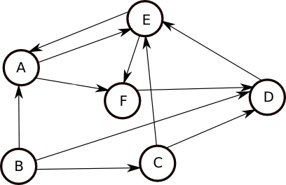
![]() “Logic units” (nodes) represent tasks that the player will perform.
“Logic units” (nodes) represent tasks that the player will perform.
![]() “Links” (lines) represent the relationship between the logic units.
“Links” (lines) represent the relationship between the logic units.
Behaviour Analysis
A node graph architecture is almost identical to an electronic circuit. When you start executing a node graph code, you are actually branching from one component (node, in our case) to an another by the rules you’ve set for the logic units, just like electric current flowing from a resistor to a capacitor. And, as you can guess, this type of signal flow is 100% linear.
When the player accomplishes a task, the node related to that event will be “expired”. In other words, it will be dead. Expired nodes cannot be resurrected. Once they’re done, they will be ignored (skipped) during code execution, forever. – Which is unlikely in electronics! An electronic component, such as a resistor, a diode, etc. cannot be conditionally turned on/off.
![]()
Back to 2002 for a “classic” implementation: Flagger
During the “Culpa Innata” development sessions, we precisely knew that we needed a node graph architecture for handling game’s complex execution flow. Many discussions were held on the method of implementation. All members of the core management & development team were expert electric/electronics engineers with no experience in video game production [Reference], but me! As a video game programmer, my perspective towards node graph theory was naturally very different, contrary to their classical approaches. I wasn’t thinking in terms of voltage, current, etc., but focused on just one thing: optimized code execution.
Thanks to my Zilog Z80 and Motorola 68000 assembly language programming background, I offered the term “Flag” for the base logic unit (node), and teamed up with Mr. Mete Balcı for 3 weeks. In December 2002, we developed a tool called “Flagger”.
Pros and Cons
Flagger was a C++ code generator with a very handy visual interface similar to UE4’s current Blueprint approach. Using Flagger, we were able to add nodes, connect them to each other, program the logic behind the nodes/links, and even take printout of the whole node graph scenario. When the visual logic design process was over, it was just a matter of selecting “Generate C++ code” from the menu, and source code was generated within minutes.
Over the following years, Flagger evolved into a more sophisticated development tool capable of handling various scenarios. Although it was a very handy tool and saved many hours during “Culpa Innata” sessions, there were a few problems with the classical node graph theory that the implementation was based on;
![]() Flags were single threaded. Only one node was allowed to execute at a time. No multi-threading.
Flags were single threaded. Only one node was allowed to execute at a time. No multi-threading.
![]() Flags were expirable. When a task was done, related flag (node) was marked as “expired”, not deleted for the sake of logic integrity.
Flags were expirable. When a task was done, related flag (node) was marked as “expired”, not deleted for the sake of logic integrity.
![]() Flags were not reusable. Once they were expired, there was no way of resurrecting them. – Inefficient memory usage, thanks to hundreds of expired nodes.
Flags were not reusable. Once they were expired, there was no way of resurrecting them. – Inefficient memory usage, thanks to hundreds of expired nodes.
![]() Flags were heavily loaded with variables. Too many dialogue related “customized” variables were defined for special cases (exceptions). – Inefficient memory usage, once again.
Flags were heavily loaded with variables. Too many dialogue related “customized” variables were defined for special cases (exceptions). – Inefficient memory usage, once again.
![]() Flag execution flow wasn’t well optimized because of node-tree search algorithm. The more nodes we had, the longer it took to accomplish the search.
Flag execution flow wasn’t well optimized because of node-tree search algorithm. The more nodes we had, the longer it took to accomplish the search.
![]() Flag execution was linear. When a node was expired, the graph code was first searching for related nodes and then retriggering the whole diagram from the beginning, like an electronic circuit simulator. – Well, that was ideal for modeling a circuit, not for developing a video game!
Flag execution was linear. When a node was expired, the graph code was first searching for related nodes and then retriggering the whole diagram from the beginning, like an electronic circuit simulator. – Well, that was ideal for modeling a circuit, not for developing a video game!
![]()
A Modern Approach: 3-bit Worker!
13 years later, I have once again found an opportunity to dive into node graph theory, and just completed implementing a new architecture for my latest video game development project. Unlike Flagger, it is something extraordinary! It is very… atypical, unconventional, unorthodox… Well, whatever… You got it 😉
First of all, it has nothing to do with classical electric/electronic circuit theory. This time, I’m on my own, and approaching the problem as a software engineer. Everything I designed/coded is based on game requirement specifications. In other words, it is implemented with “practical usage” in mind.
![]() I have defined the basic logic unit (node), as a “worker”. – (Due to functional similarities, I simply borrowed this term from Web Workers.)
I have defined the basic logic unit (node), as a “worker”. – (Due to functional similarities, I simply borrowed this term from Web Workers.)
![]() A worker is a background task with adjustable priority settings. It performs/responds like a hardware interrupt.
A worker is a background task with adjustable priority settings. It performs/responds like a hardware interrupt.
![]() Each worker is multi-threaded.
Each worker is multi-threaded.
![]() Depending on conditional requirements, a worker can expire and/or live forever. If expired, it can be resurrected and/or reinitialized, while preserving its previous state. So, a worker is a 100% reusable node.
Depending on conditional requirements, a worker can expire and/or live forever. If expired, it can be resurrected and/or reinitialized, while preserving its previous state. So, a worker is a 100% reusable node.

![]() Each worker uses only 3-bits! No additional variables, no references, nothing else. – (If necessary, a worker offers flexible architecture for additional variables. However, I find it totally unnecessary. 3-bits are more than enough!)
Each worker uses only 3-bits! No additional variables, no references, nothing else. – (If necessary, a worker offers flexible architecture for additional variables. However, I find it totally unnecessary. 3-bits are more than enough!)
![]() Workers are object oriented. They can easily be inherited.
Workers are object oriented. They can easily be inherited.
![]() Inherited workers don’t need additional logic variables. All child workers share the same 3-bit information that they inherited from their parents!
Inherited workers don’t need additional logic variables. All child workers share the same 3-bit information that they inherited from their parents!
![]() Each worker has a time dependent linear workflow. Just like a reel-to-reel tape recorder, it can be played, paused, slowed down, accelerated, fast forwarded, rewinded, and stopped.
Each worker has a time dependent linear workflow. Just like a reel-to-reel tape recorder, it can be played, paused, slowed down, accelerated, fast forwarded, rewinded, and stopped.
![]() Workers can be non-linearly linked to other Workers! Which means, node-tree search algorithms are no more necessary. There is no “main loop” for executing nodes! Code execution is pre-cached for optimum performance.
Workers can be non-linearly linked to other Workers! Which means, node-tree search algorithms are no more necessary. There is no “main loop” for executing nodes! Code execution is pre-cached for optimum performance.
![]() Workers are optimized for event driven methodology. No matter how many concurrent active workers (threads) you have in the scene, there is practically no CPU overhead. Ideal for mobile scenarios.
Workers are optimized for event driven methodology. No matter how many concurrent active workers (threads) you have in the scene, there is practically no CPU overhead. Ideal for mobile scenarios.
![]() Workers are managed by “Managers”. A Manager is inherited from base Worker node. So, any worker can be assigned as a Manager.
Workers are managed by “Managers”. A Manager is inherited from base Worker node. So, any worker can be assigned as a Manager.
![]() Workers can communicate with each other and access shared variables via Managers.
Workers can communicate with each other and access shared variables via Managers.
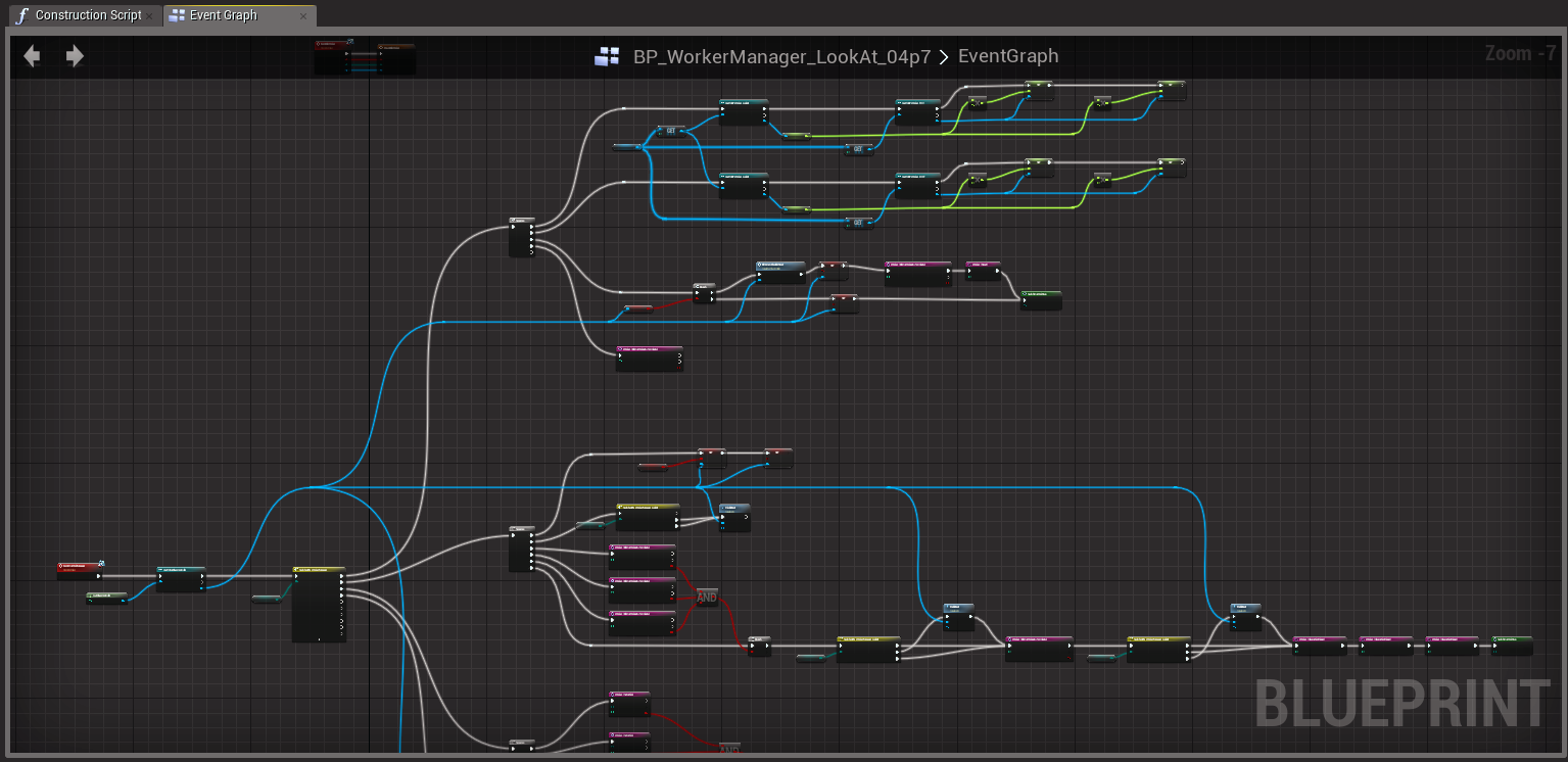
![]() Whole architecture is 100% platform independent. For a showcase, I’ve implemented it for Unreal Engine 4 using C++ and Blueprints. It can easily be ported to other game engines; such as Unity, CryEngine, etc.
Whole architecture is 100% platform independent. For a showcase, I’ve implemented it for Unreal Engine 4 using C++ and Blueprints. It can easily be ported to other game engines; such as Unity, CryEngine, etc.
![]() And, most important of all, everything is meticulously tested. – It’s working as of today 🙂
And, most important of all, everything is meticulously tested. – It’s working as of today 🙂
![]()
Any drawbacks?
Sure… Due to complexity of comprehending “a set of non-linearly linked time dependent linear nodes”, debugging can be a nightmare. As always, designing simplified and organized logic sets reduces potential problems. – I keep my logic sets neat and tidy 😉
So, what’s next?
Well, to be honest, since all theoretical stuff is done, I’ll switch to game content development. I am quite sure that I’ll keep on adding/removing things to my 3-bit node graph architecture. I will keep on improving it while preserving its simplicity, for sure.
“It is vain to do with more what can be done with less.” – (William of Ockham)